

Introduction
In the field of globally collaborative precision manufacturing, an email stating “require high quality” or a drawing merely annotated with “smooth surface” is enough to create a huge understanding gap between teams from different cultural backgrounds. This ambiguity, stemming from the difference between everyday English and technical English, often leads to repeated part rework, severe project delays, and ultimately, deliverables that are far from the design intent. Research shows that the hidden costs caused by this inefficient communication can account for up to 27% of the total project budget.
This article will delve into the most common pitfalls in technical communication for precision manufacturing and provide a set of standardized strategies for transforming subjective intentions into objective, executable instructions, helping project managers plug this astonishing budget leak.
Is Your Definition of “Quality” the Same as Your Manufacturer’s?
Abstract Vocabulary: The “Black Hole” in Precision Manufacturing Communication
At the project initiation stage, seemingly clear requirements like “high quality” or “good finish” are actually the most challenging communication problems for CNC milling services providers. These abstract terms act like a “semantic black hole,” where their specific meaning depends entirely on the subjective understanding of each party. The buyer might mean absolute dimensional accuracy and zero defects, while the manufacturing team might interpret it as the absence of visible tool marks.
This cognitive bias directly leads to a serious consequence: manufacturers cannot extract any executable, verifiable technical criteria from these descriptions, ultimately forcing them to rely on experience to “guess,” planting huge risks for project delivery.
From Subjective Expectations to Objective Standards: The Quantification Revolution of Quality
The only way to resolve this dilemma is to completely abandon subjective adjectives and delegate the definition of “quality” to objective, quantifiable international standards. The cornerstone of this lies in a clearly annotated technical drawings.
- Quantification of Surface Treatment
Instead of using “smooth surface,” clearly specify the surface roughness Ra value, for example, “All exterior surfaces: Ra ≤ 0.8 μm.” This value is directly linked to the American Society of Mechanical Engineers (ASME) 1 surface texture standard, providing an indisputable basis for inspection. - Clarification of Dimensional Accuracy
“High precision” should be transformed into specific tolerance instructions, such as “All critical dimensions must be strictly controlled within ±0.05mm according to the drawing’s GD&T requirements.”
- Authoritative Reference to Standards
Directly stating “Part manufacturing must comply with the ISO 2768-m medium precision tolerance standard” in the drawing notes can effectively unify both parties’ framework for what constitutes “acceptable.”
Practical Case: How to Convert “High Quality” into Instructions
A complete example of a converted quality instruction is as follows: “In drawing revision A-001, the tolerances for all features designated as characteristic dimensions must strictly adhere to the GD&T frame definitions; the surface roughness of Datum A must achieve Ra 0.4 μm and comply with the ASME B46.1 standard; the final part must pass CMM inspection and provide a First Article Inspection Report based on the AS9102 standard.”
This precise expression allows any qualified CNC milling services supplier to clearly understand the requirements and provide accurate execution plans and quotes, fundamentally eliminating cost waste caused by ambiguity.
How Can “Standard Material” Lead to Catastrophic Failure?
During Rapid Prototyping or small-batch trial production, using non-standard terms like “standard plastic” or “aircraft aluminum” for the sake of simplicity is another fatal trap. The mechanical properties, corrosion resistance, and machinability of manufacturing materials vary greatly. For example, “aircraft aluminum” could refer to various grades such as 2024, 6061, or 7075, each with different properties and heat treatment states. A vague reference could lead to catastrophic failure of the prototype during testing.
The only way to ensure material consistency is to mandate the use of internationally recognized standard material grades. It is essential to explicitly specify complete designations like “Aluminum 6061-T6” or “Stainless Steel 304.” For critical projects, suppliers should be required to provide material certifications (e.g., Mill Certificate) to ensure material source and composition are correct. Engineers can include links to MatWeb (a well-known online material database) in communications as a common benchmark for discussing material parameters. This precision is crucial for ensuring the functionality and safety of the parts.
What’s the Critical Mistake Everyone Makes with Tolerances on Drawings?
Why Default Tolerances Are the Silent Killer of Precision Machining?
Many engineers rely on default tolerances on drawings or simple annotations like “±0.1,” but this is precisely a fatal trap for high precision CNC milling projects. Such linear tolerances only control the extreme values of dimensions but cannot constrain the form of the part (like flatness, roundness) or the relative positions between features (like the distribution pattern of a hole pattern). The latter is often the core of ensuring the part’s assembly functionality.
- Dimensional Tolerance ≠ Functional Control
A shaft labeled with a diameter of 10±0.1mm might be unable to fit into its mating hole due to excessive ovality. - The Root Cause of Assembly Failure
The center distance between two holes might meet the ±0.1mm requirement, but if the position is out of control, bolts still cannot pass through simultaneously. - Unnecessary Cost Waste
Over-tightening tolerances for non-critical features forces the precision CNCmilling machine to adopt more time-consuming processes, unnecessarily increasing processing costs by up to 30%.
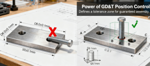
Figure2: Why ± isn’t enough: This direct comparison shows how GD&T’s position tolerance creates a cylindrical zone that guarantees part functionality, while linear tolerances alone can lead to assembly failures even when dimensions are “in spec.”
GD&T: The Engineering Consensus Beyond Language
GD&T (Geometric Dimensioning and Tolerancing) is the ultimate solution to crack this dilemma. This symbolic language, based on the International Organization for Standardization (ISO) ISO 1101 standard, ensures part assembly function by controlling elements like position and profile. It transcends any description in natural language and is a universal engineering grammar based on symbols. Partnering with manufacturers certified to standards like AS9100D or IATF 16949 is crucial, as these systems mandate standardized interpretation and inspection of GD&T.
Are You Asking the Right Questions in Your Quotation Emails?
A vague Request for Quotation (RFQ) inevitably leads to an inaccurate quote. A professional CNC machining inquiry is not just about asking for the price; it’s about establishing clear quality and delivery expectations through specific questions. This is crucial for the success of custom CNC milling projects.
A professional RFQ framework should include the following core elements: First, clear technical requirements, meaning attaching drawings with complete GD&T and standard material grades. Second, specific quality verification requirements. Finally, clear deliverable definitions, including packaging methods and surface treatment requirements. A detailed RFQ is the cornerstone of a successful project. This is crucial for the success of precision CNC milling projects. To gain a deeper understanding of its complexities, you can refer to this detailed guide.
Beyond Text: What Visual Tools Can Seal the Communication Loop?
Even if the textual description is extremely precise, there may still be blind spots in communicating complex geometries. In complex CNC milling applications such as medical or aerospace, fully utilizing visual tools is the last line of defense for ensuring fail-safe communication.
It is recommended that both communicating parties go beyond plain text and make full use of visual aids: First, attach enlarged views of key areas in the drawings to clearly show small or complex features. Second, directly share annotated 3D model screenshots or screen recordings to visually explain key mating surfaces and important areas, serving as a supplement to the drawings. Finally, if there is a “golden sample” or a competitor’s sample, providing multi-angle photos and pointing out aspects to imitate or avoid can greatly facilitate mutual understanding.
In the field of precision CNC milling,,this “visual + data” dual communication model can maximize the reduction of ambiguity. Choosing a partner with strict aviation certifications like AS9100D is key to ensuring controlled communication and delivery from start to finish. You can learn about their comprehensive CNC Milling capabilities here.
Conclusion
In the international collaboration of precision manufacturing, precise technical English is not an option but a necessity. It transforms subjective expectations into objective, verifiable instructions, becoming a reliable bridge connecting ideas with physical objects. By mandating the use of standardized terminology, quantifying technical requirements, and introducing visual aids, project teams can completely eliminate that 27% hidden cost, ensuring project budget and schedule are fully under control.
When choosing a manufacturing partner, priority should be given to suppliers like JS Precision that possess a sound international quality certification system (such as ISO 9001, ISO 14001, IATF 16949, ISO 13485, AS9100D). Their standardized processes are the critical first step to ensuring clear communication and consistent quality.
Author Bio
This article was written by a senior expert in the precision manufacturing field. The author has over 15 years of practical experience in CNC machining.The author is currently employed by a leading industry company, which holds multiple international quality management system certifications such as ISO 9001, ISO 13485, and AS9100D, ensuring full-process standardization and precision from technical communication to product delivery.
H2: FAQs
Q1: What is the biggest mistake in technical English for manufacturing?
A: Using subjective adjectives like “smooth” or “strong” instead of quantifiable metrics. Specifying “Ra 0.8 μm surface finish” or “6061 aluminum” is unambiguous and prevents costly errors in custom CNC milling projects.
Q2: How can I ensure my GD&T symbols are understood correctly?
A: Reference the international standard (ISO 1101) in your drawing notes and use consistent datum feature symbols. For high precision CNC milling, clearly defining the primary datum is crucial for part functionality.
Q3: Why is a detailed RFQ (Request for Quotation) so important?
A: A detailed RFQ sets clear expectations from the start. It outlines materials, quantities, critical tolerances, and quality checks, allowing CNC milling services to provide accurate pricing and timelines, reducing surprises later.
Q4: Can I use a translation app for technical drawings?
A: While helpful for single words, translation apps often fail with technical jargon and context. Relying on them for complex GD&T or material specs is risky. Standardized symbols and direct communication are safer.
Q5: What should I look for in an international manufacturing partner?
A: Seek partners with relevant international quality certifications (like ISO 9001, AS9100D), proven experience in your industry, and a demonstrated commitment to clear, proactive communication throughout the process.